


Introduction
METAFORSA SMART HOUSE Installation Manual describes the procedure for its installation, assembly, operation and setting. While working with the system, you must strictly comply with all the requirements set out in this manual. Failure to comply may result in damage to the device, its failure, electric shock, fire and other fallout. The manufacturer reserves the right to make changes to this manual without prior notice. This manual is an integral part of the system and shall remain with the end-use customer.
Features
- 10 universal outputs support:
- Lights
- NC/NO heating valves
- Blinds
- 1 or 2-pole gates
- 1 or 2-pole valves
- NC/NO locks
- Fan coil units
- 4 dimming outputs
- 24 Discreet inputs that support:
- Buttons
- Switches
- reed switches
- leak sensors
- motion detectors
- 4 digital inputs for up to 8 temperature sensors
- Extension port
- Relays with AgSnO2 contacts rated for 80A 20ms inrush current
- Cloud connection and control of all house systems
- Voice control (Siri, Alexa, Google Home)
- Plugins engine allows expanding the system possibilities (e.g. integrating with Satel, Philips Hue, IKEA lights)
- Safety against unauthorized intrusion ensured with RSA/AES256 encryption
- Push notifications from the system on your phone (also possible to receive through Telegram and Viber messengers)
- History (meter data for 1 year is stored)
- Plug and play (possibility for fast and user-friendly extension of the system)
- Regular system updates
- Large constantly updated database of scripts to meet all your needs
- Automatic daily backups via cloud with the possibility to restore the initial configuration
- Open API (which allows integrating Larnitech into other systems)
- Interactive and user-friendly LT SETUP Web interface available for advanced configuration
- Plug and play
- It is a completely ready-to-install Smart Home system kit
Safety requirements
CAUTION! All work related to the installation, connection, setting up, service and support must be carried out by qualified personnel with sufficient skills and experience in working with electrical equipment.To avoid the risk of fire, electric shock, damage to the system and / or personal injury, the system installation and assembly must be performed in accordance with the instructions listed below:
- all connection works must be carried out without power;
- use appropriate tools and personal protection against electric shock;
- do not use damaged cables, wires and connectors;
- avoid folding of cables and wires;
- do not pinch or kink the cables and wires by applying excessive force. Otherwise, inner conductors of the cable and wires may be stripped or broken;
- do not use the power socket with poor contacts to connect;
- do not exceed the load parameters limit specified in this manual;
- the supply conductors wire section is subject to the specifications for current density limit, insulation type and wire material. Light section can result in cable overheating and fire.
When working with the system after voltage supply NEVER:
- make connection/disconnection of connectors;
- open modules and sensors.
System configuration and purpose
Purpose of the system
METAFORSA SMART HOUSE is a ready-made solution for automation of residential and commercial premises, hotel complexes which includes the most highly desired features of Smart House.
The device has 10 control channels, 4 dimming channels, 24 incoming sensor channels, and a digital sensors’ connection port.
| Universal outputs can be used to control: | Universal inputs allow you to connect: |
|---|---|
| Lighting | Buttons/switching units |
| Socket connectors | Magnetic reed switches |
| Underfloor heating | Magnetic reed switches |
| Curtain/gate actuators | Leakage sensors |
| Water supply/heating valves |
Digital sensors connection port
The digital sensors connection port allows you to connect a variety of digital sensors, such as temperature sensors, ambient light, humidity and other.
Expansion port
The expansion port allows you to upgrade the system by connecting auxiliary equipment, such as the control module for LED lighting, dimming, metering devices and other elements. The package, which is completely ready-to-install, includes the basic hardware and software.
Package contents
The package comes standard with:
| Mainframe METAFORSA MF-14.А | 1 pc |
| Power supply unit MEANWELL DR-15-12 | 1 pc |
| Motion sensor CW-MSD | 3 pcs |
| Leakage sensor FW-WL.A | 2 pcs |
| Temperature-sensitive element FW-TS.A | 4 pcs |
| Magnetic reed switch (window/door position sensor) | 4 pcs |
| Ethernet-cable noise filter | 1 pc |
| Power supply cord | 1 pc |
| Manual | 1 pc |
Basic technical specifications of the System
The basic specifications and characteristics of the module METAFORSA MF-14.A are shown in table 1
| Specification | Meaning |
|---|---|
| Output ports | |
| Number of switched channels | 10 |
| Number of switched groups | 10 |
| Number of dimming channels | 4 |
| Commutation voltage | 0-250 V AC/DC |
| Peak load (one channel) | 16A |
| Peak load (device) | 160A |
| Max load per dimming channel | 0.5A (110W at 220V) |
| Dimmer type | MOSFET |
| Dimming type | trailing edge |
| Power supply cable connection type | connector |
| Permissible section of power supply cable to connect in socket: single-conductor cable multiple-conductor cable tipped multiple-conductor cable | 0.5 … 4mm2 0.5 … 4mm2 0.5 … 2.5mm2 |
| Input ports | |
| Number of discrete inputs | 24 |
| Number of digital inputs | 4 |
| Current maximum rating on the direct-current voltage connectors | 50mA |
| Other | |
| Operating ambient temperature | 0 … +45°С |
| Storage/transportation temperature | -20 … +60°С |
| Permissible humidity | 0 … 95% (non-condensing) |
| Power supply | 12 … 27.5 V DC 24V, 0.75A Recommended |
| Maximum demand | 0.5А |
| Available interfaces | Ethernet, CAN, OneWire |
| Bus type | CAN (4-wire) |
| CAN (4-wire) | 800 m* (twisted pair 5 cat) |
| CAN wire type | FTP Cat 5E |
| CAN connection type | connector |
| Digital line maximum length | 30 m |
| Digital line wirde type | UTP/FTP Cat 5E |
| LAN maximum length | 100 m |
| LAN wire type | UTP/FTP Cat 5E |
| LAN connection type | Connector RJ-45 |
| Dimensional specifications | 9U, 156x110x58 mm |
| Shell material | ABS plastic |
| Casing | IP40 |
| Equipment installation type | DIN-rail (EN 60715) |
| Weight | 400 g |
* – installing additional power supply units is required for long lines; the maximum length of the line may be reduced by various interference factors
General structure of the System
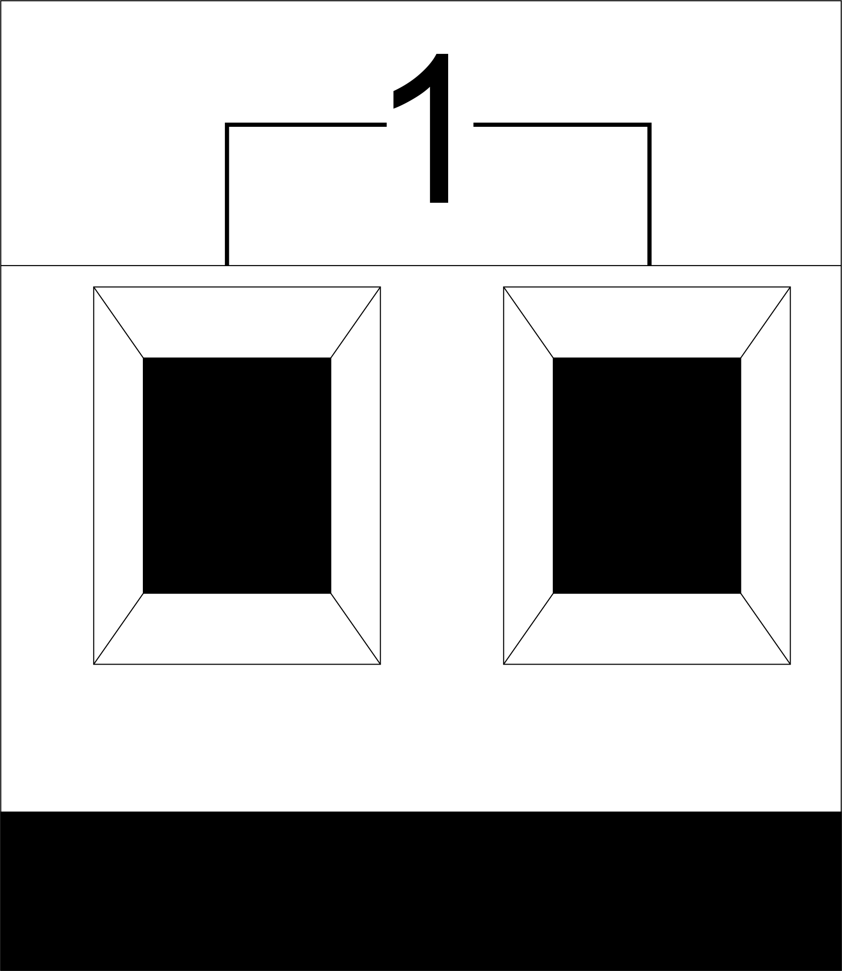
Module general view is shown in fig. 1

| 1 | — connector for load application and power supply |
| 2 | — connector for dimming-lamps application |
| 3 | — power connector |
| 4 | — Ethernet network connector |
| 5-6 | — connectors for digital sensors and buttons/switching units |
| 7 | — OneWire interface connector (for digital sensors) |
| 8 | — connector for expansion module. |
Overview of the METAFORSA device external connectors: At the top of the casing (fig. 1) there is:
- connector (1) — Devices connection;
- connector (2) — Dimming lamps connection;
At the bottom of the casing (fig. 1) there is:
- connector (3) — module power supply connection;
- connector (4) — Ethernet network connection;
- connectors (5-6) — four six-point connectors for digital sensors connection – motion, leakage, reed switch sensors, and *button/switching unit sensors;
- connector (7) — OneWire digital sensors bus connection;
- connector (8) — expansion module connection.
The physical configuration and contact point assignment of each connector are shown in table 2.
| Connector | Contact | Assignment |
|---|---|---|
 | 1-10 | Load application (light lamps, thermal actuators, etc.) |
| D1-4, L, N | Load application (dimming lamps) | |
| Device status indicators | The module status indicators are described in table 3 | |
 | +24V GND | +24V — module power supply by an external 24 V power supply GND — common |
 | RJ45 | Connector for LAN connectivity |
| In1-12, In13-24 GND | Controlling devices connection (buttons, magnetic reed switches, motion or leakage sensors): +12V — sensor power output +12 V In1 … In24 — logic inputs (0-12 V) GND — common | |
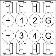 | OneWire | Digital sensors connection (temperature) VCC — sensors power supply output +5V OW1-OW4 — OneWire data buses GND — common |
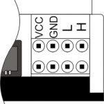 | VCC GND L H | External modules connection for CAN-bus VСС — 12V output for external devices power supply GND — common L — CAN-L data bus H — CAN-H data bus |
| Indicator | Status | Description |
|---|---|---|
| Power | Power | |
| Power not available | ||
| Activity | Data communication | |
| Data communication not available | ||
| Error | No errors | |
| Communication error | ||
| Module overheat | ||
| Dimmer outputs module overload | ||
| Absence of power on dimmers, if in configuration |
System installation and assembly
Before connecting the system, you must:
- site the sensor and actuators (if not pre-installed), set the sensors and actuators;
- site the module and power supply.
Note: The module must be installed near the power supply voltage source.
- The power of circuit breaker assembly must comply with the load capacity;
- Nothing else than the phase conductors can be connected to the module, the neutral wire is connected separately.
Typical diagram of METAFORSA MF-14.A module connection is shown in fig. 3.

Connection of the actuators
Connection of the lights/electric contactor/heating thermal actuator
 Fig. 4 | Such actuators as light, electric contactor, heating thermal actuator should be switched on any of the outputs 1 – 10, the neutral wire and the ground wire should be connected directly to the switchboard. The example of connection is shown in Fig.4. |
Connection of high load device
 | Recomended contactors:
|
Connection of single-pole water/gas supply valve
| Caution: Before applying power to the load, make sure that the output configuration of METAFORSA module is correct. The incorrect configuration or incorrect connection can cause the module failure and/or failure of the equipment connected to it, and even a fire. | |
 Fig. 5 | The single pole water/gas supply valve is connected to any of the outputs of 1 – 10, the (neutral wire and the ground wire are connected directly to the switchboard. The example of connection is shown in Fig.5. |
Connection of double-pole water/gas supply valve
| Caution: Before applying power to the valve, it is necessary to ensure the output configuration of METAFORSA module is correct. The incorrect configuration can cause the voltage application simultaneously to both channels of the valve, which may result in the module failure and/or failure of the equipment connected to it, and even a fire. | |
 Fig. 6 | Two adjacent contact points (for example, 3, 4) are used to connect the double-pole water/gas supply valve; in these conditions the neutral wire and the ground wire are connected directly to the switchboard. The example of connection is shown in Fig.6. |
Connection of single-pole gate actuator
| Caution: Before applying power to the module, you should properly configure access to the application. The contacts incorrectly configured can result in the module failure and/or failure of the equipment connected to it, and even a fire. | |
 Fig. 7 | Any contact point (for example, 3) is used to connect the single-pole gate drive controllers. The example of connection is shown in Fig.7. |
Connection of double-pole gate actuator
| Caution: Before applying power to the module, you must properly configure the outputs in the application. The contacts configured incorrectly can lead to simultaneous power supply to both channels, resulting in the module failure and/or failure of the equipment connected to it, and even a fire. | |
 Fig. 8 | Two adjacent contact points (for example, 3, 4) should be used to connect the double-pole gate drive controller. The example of connection is shown in Fig.8. |
Connection of curtain/jalousie/shutter actuator with 220V force control
| Caution: Before applying power to the module, you must properly configure the outputs in the application. The contacts configured incorrectly can lead to simultaneous power supply to both channels, resulting in the module failure and/or failure of the equipment connected to it, and even a fire. | |
 Fig. 9 | Two adjacent contact points (for example, 3, 4) should be used to connect the curtain/jalousie/rolladens actuator, in these conditions the neutral wire and the ground wire are connected directly to the switchboard. The example of connection is shown in Fig.9. |
Connection of curtain/jalousie/shutter actuator with low-voltage control
| Caution: Before applying power to the module, you must properly configure the outputs in the application. The contacts configured incorrectly can lead to simultaneous power supply to both channels, resulting in the module failure and/or failure of the equipment connected to it, and even a fire. | |
 Fig. 10 | Two adjacent contact points (for example, 3, 4) should be used to connect the curtain/jalousie/rolladens actuator with low-voltage control. The example of connection is shown in Fig.10. |
Connection of sensing elements/switches/buttons
Connection of motion sensors
The motion sensors should be connected to any free input in1-in24; in these conditions their power is connected to the contact points of +12V and GND of the relevant group. The example of connection is shown in Fig.11.

Fig. 11
Connection of FW-WL.A leakage sensors
FW-WL.A leakage sensors are connected to any free input in1 – in24, in these conditions the power should be connected to +12V and GND points of the relevant group. The example of connection is shown in fig. 12.
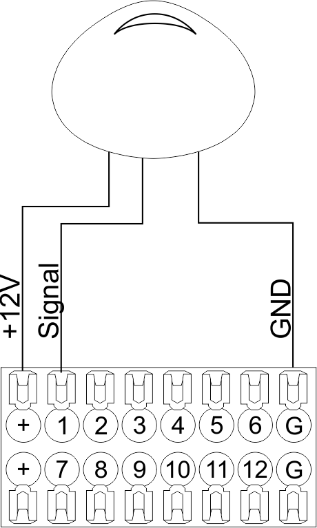 Fig12 | 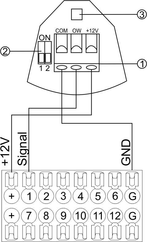 Fig13 |
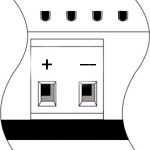
Configuration and connection of the FW-WL.A sensor 1. Terminals:
- +12V — sensor power is connected to the contact point of METAFORSA “+12V”;
- OW — sensor pickup signal;
- GND — common, connected to GND contact of METAFORSA.
2. Sensor preset switch (optionally):
- 1 — sensor sensitivity (ON – high, OFF – low);
- 2 — indicator colour setting (ON – blue, OFF – green).
3. LED status indicator.
Connection of buttons/switches/magnetic reed switches
Buttons and reed switches are connected to any free input in1-in24, while their second contact point is connected to GND point of the relevant METAFORSA module group, + 12V power outputs – not in use. The example of connection is shown in Fig. 14-15.
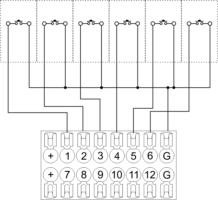 Fig14 connection of buttons/switching units | 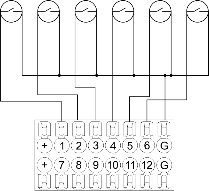 Fig15 connection of the magnetic reed switches (window/door position sensors) |
Connection of digital sensors
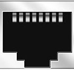
The OW adapter (Fig. 16a) is supplied along with METAFORSA module with the possibility to connect up to 8 digital sensors to it. In these conditions, several devices can be connected to one channel (Fig. 16b). The connected sensors are detected automatically and do not require any original setting.
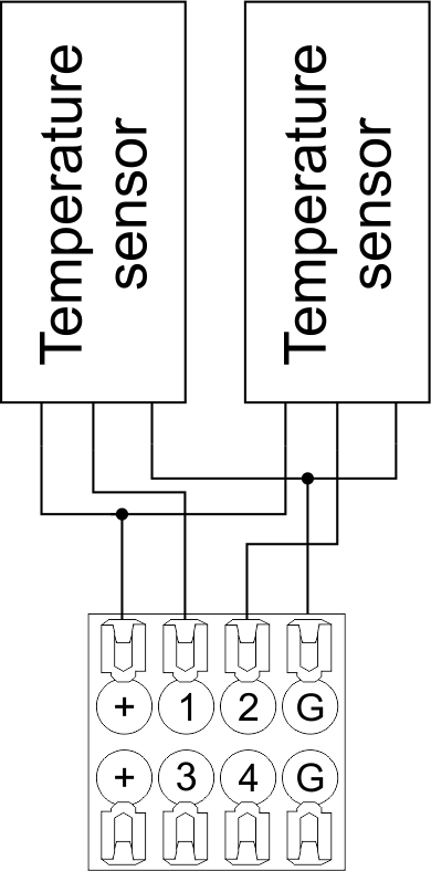 Fig16 a | 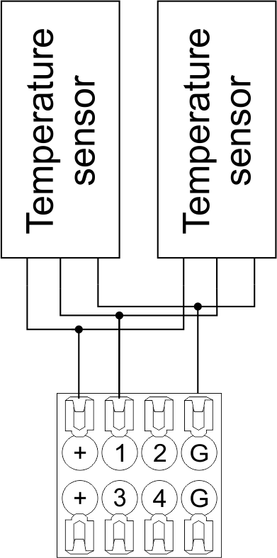 Fig16 b |
Configuration and connection of the OW adapter
Caution: Ensure the connection is correct. The incorrect connection may cause sensor and/or module malfunction.Connection of auxiliary equipment.
Expansion modules include Larnitech equipment connected through the CAN-bus. Such equipment includes: dimmers, RGB-backlit control modules, multimode sensors, etc. The equipment connected to the expansion port is defined automatically and does not require any preset tuning. Connector contact pin assignment is defined in Table 4. The example of connection is shown in Fig. 17.
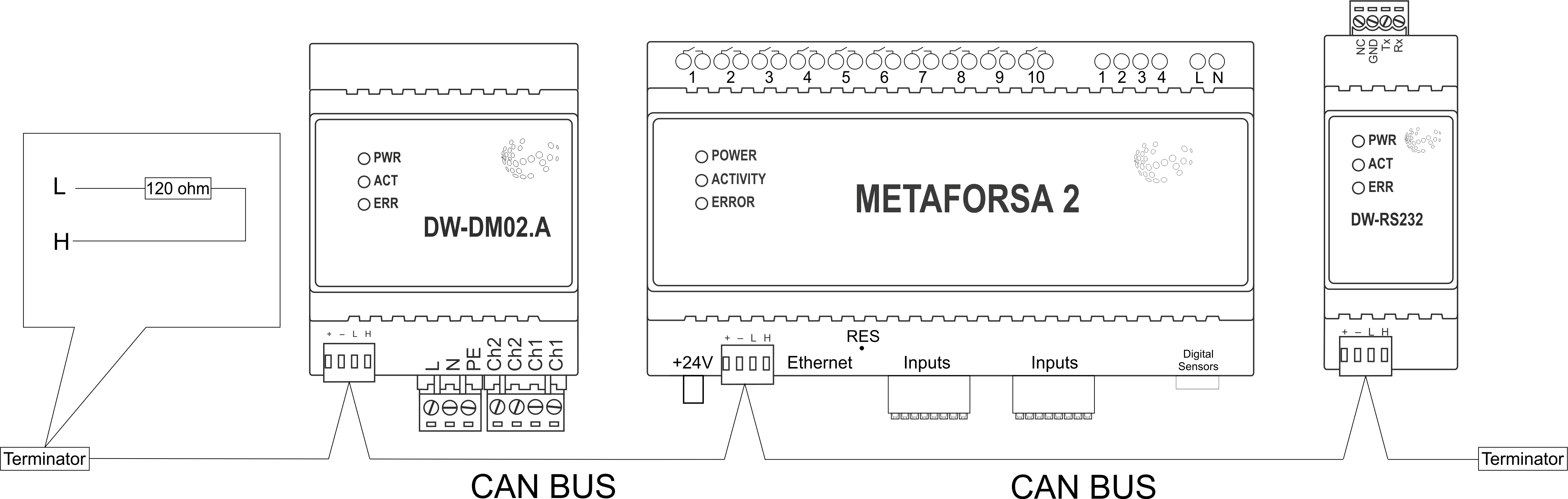 |
| Caution! The 120 ohm terminating resistors should be installed at the end connectors between L and H contact points of CAN-bus. Ensure the connection is correct. The incorrect connection may cause sensor and/or module malfunction. |
Module installation and connection procedure
ATTENTION! You must precisely follow the recommendations listed in the Security Requirements section hereof.- Install the module in the switchboard on the DIN-rail and fix it with the special latch on the module base.
- Fasten the supply unit on the left side of the module.
- Connect the connector (4) having the noise filter pre-installed which is supplied complete with the module.
- Connect the connectors (5), (6).
- Connect the connectors (1), (2).
- Connect the connector (3).
- Apply power to the supply unit of METAFORSA module.
- Wait until the module is loaded, then configure it in accordance with the System Setup Instructions.
- Apply power to the connectors (1), (2).
- Check all equipment for proper operation.
METAFORSA module shut-off and deinstallation procedure
- De-energize the module by disconnecting the circuit breaker assembly of the load power supply and METAFORSA module supply unit. Verify the voltage is absent on the terminals (1), (2) of the connector wires and on the input terminals of the supply unit.
- Disconnect the load power supply connectors (1), (2).
- Disconnect the connector (3).
- Disconnect the connectors (4)-(6).
- Remove the module from the DIN-rail, releasing the latch at the bottom of the module base.
Hardware setup
To configure and control METAFORSA SMART HOUSE, you must install Larnitech software on your smartphone or tablet, which is available in App Store and Play Market. After installation, follow the System Setup Instructions.
Fault diagnostics and handling
The following are some possible faults and ways of fault handling. If you have any difficulty, or face the fault undeclared here, please contact the Technical Support: [1] or [support@larnitech.com]. There are also some tips in the FAQ section at our website [2].
The actuators do not operate:
- ensure the outputs are properly configured in the application (see System Setup Instructions);
- check the connection is correct in accordance with table 2 and paragraph 3.6;
- ensure the power is supplied to the input power contact , i.e. all circuit breaker assembly are ON.
- verify the operability of the connected equipment.
The module is off, indication absent:
- check the connection to 24V supply unit as shown in table 2 (contacts pin assignment);
- check the connection of the supply unit to 220V power mains, the indicator should be ON.
Network connection fault:
- ensure the Ethernet cable is properly wired and connected to the connector;
- ensure the LED status indicators are ON on the Ethernet connector;
- check the LAN configuration is correct, Ethernet cable loops are absent;
- METAFORSA module and the device you are connecting from are in the same network.
hold integer 0-10000 1-10 by default hold is the same as runtime hold is the bridging time in miliseconds, is used for gate and jalousie, lock; Example: hold=3500
The sensors do not operate:
- ensure the inputs are properly configured in the application (System Setup Instructions);
- check the connection is correct in accordance with table 2 and paragraph 3.7;
- ensure the METAFORSA module is ON: circuit breaker assembly is closed, indication on the supply unit is ON, the module indication corresponds to the operating status – table 3;
- check the power supply availability on the sensors;
- check the integrity of lines laid to the sensors.
The auxiliary equipment does not operate:
- check the connection is correct in accordance with table 2 and paragraph 3.8-9;
- ensure the METAFORSA module is ON: circuit breaker assembly is closed, indication on the supply unit is ON, the module indication corresponds to the operating status – table 3;
- check the integrity of the CAN lines, voltage supply on the modules.
HW Settings
| Name | Type, range | SUBID | Default | Description |
|---|---|---|---|---|
| runtime | integer 0-100 | 1-10 | 15 | runtime is the open/close time in seconds, is used for jalousie, gate, valve(2 pole);
|
| runtimeopen | integer 0-60000 | Blinds subId | Runtimeopen is the open time in milliseconds, is used for blinds; Example: runtimeopen=15000 | |
| runtimeclose | integer 0-60000 | Blinds subId | Runtimeclose is the close time in milliseconds, is used for blinds; Example: runtimeclose=15000 | |
| hold | integer 0-10000 | 1-10 | 500 | hold is the bridging time in milliseconds, is used for gate and jalousie (by default hold is the same as runtime for jalousie and gate), lock; Example: hold=3500 |
| def | string 'ON' | 1-10 | 'OFF' | def is the element status is set after restart, is used for lamp, heating, valve(1 pole); Example: def='ON' |
| stop | Char ‘R’ | 1-7 | – | (for 2-pole gate and blinds) If it is declared then by Stop command during the motion, the same impulse appears as it was at the beginning of the motion. Pole, an which the stop-impules is formed, is defined by the parameter Stop value. If it is ‘r’ or ‘R’ then stop-impulse is produced on the opposite to the start-impulse pole. If any other value is delcared (e.g., ‘d’ ) then the stop-impulse is on the same pole. If a Runtime passed after the beginning of the motion then the stop-impulse is not formed. Example: stop=’r’ |
| out | char[10] | 98 | 'LLLLHHHHP-' | Each char is responsible for the type of a particular channel
Example: out='LLB-G-V-W-' |
| dm | char[4] | 98 | ‘LLLL’ | Each char is responsible for the type of a particular channel
Example: dm=’skl-‘ |
| def | integer 0-250 | 11-14 | 100 | The default brightness level in case of a power reset (1..250). Example: def=250 |
| min | integer 0-100 | 11-14 | 0 | Minimum dimming level, example: min=10 |
| max | integer 0-100 | 11-14 | 100 | Maximum dimming level, example max=95 |
| start | integer 0-100 | 11-14 | 0 | The Start function is used for lamps that lack the minimal voltage to get turned on. If the set value is lower than the start value, the lamp is turned on at the start value and them the light is dimmed down to the set level. Example: start=60 |
| force | integer 0-100 | 11-14 | 10 | Time duration of the starting value (measured in milliseconds). Example: force=20 |
| runtime | integer 0-60000 | 11-14 | 1000 | Runtime is the speed of changing the brightness from ‘min’ to ‘max’ (measured in milliseconds). Example: runtime=1000 |
| offset | integer (+/- 0…39) | 39-46 | '0' | sensor values offset; For example, offset is -3.8 : Example: hw="offset='-3.8'" |
| in | char[24] | 98 | 'BBBBBBBBBBBBMMMLLLKKKKKK' | Each char is responsible for the type of a particular channel
Example: in='MMMMMMMMMMMMLLLLLLLLLLLL' 12 motion sensors and 12 leak-sensors; in='BBBBBBBBSSSSSSBBBBSSSSSS' 12 buttons; 12 switches. |
 1<item addr="339:1" auto-period="600" cfgid="40" hw="def='ON'" name="Lamp" type="lamp" uniq_id="3779">
 2<item addr="339:2" cfgid="40" hw="def='ON'" name="Radiator" type="valve-heating" uniq_id="3780">
 3    <automation name="Eco" temperature-level="16" uniq_id="3781"/>
 4    <automation name="Comfort" temperature-level="22" uniq_id="3782"/>
 5    <automation name="Hot" temperature-level="25" uniq_id="3783"/>
 6</item>
 7<item addr="339:3" cfgid="40" hw="runtime=9" name="Jalousie" sub-type="120" type="jalousie" uniq_id="32"/>
 8<item addr="339:5" cfgid="40" hw="runtime=13" name="Gate" sub-type="120" type="gate" uniq_id="3784"/>
 9<item addr="339:7" cfgid="40" hw="hold=4600" name="Gate" sub-type="120" type="gate" uniq_id="3785"/>
10<item addr="339:8" cfgid="40" hw="runtime=10" name="Valve" type="valve" uniq_id="3786"/>
11<item addr="339:11" cfgid="40" name="Motion" type="motion-sensor" uniq_id="17"/>
12<item addr="339:12" cfgid="40" name="Motion" type="motion-sensor" uniq_id="18"/>
13<item addr="339:13" cfgid="40" name="Motion" type="motion-sensor" uniq_id="19"/>
14<item addr="339:16" cfgid="40" name="Leak" type="leak-sensor" uniq_id="21"/>
15<item addr="339:17" cfgid="40" name="Leak" type="leak-sensor" uniq_id="41"/>
16<item addr="339:19" cfgid="40" name="Switch" type="switch" uniq_id="22"/>
17<item addr="339:20" cfgid="40" name="Switch" type="switch" uniq_id="23"/>
18<item addr="339:21" cfgid="40" name="Switch" type="switch" uniq_id="24"/>
19<item addr="339:22" cfgid="40" name="Switch" type="switch" uniq_id="25"/>
20<item addr="339:23" cfgid="40" name="Door" type="door-sensor" uniq_id="26"/>
21<item addr="339:24" cfgid="40" name="Door" type="door-sensor" uniq_id="27"/>
22<item addr="339:25" cfgid="40" name="Door" type="door-sensor" uniq_id="28"/>
23<item addr="339:26" cfgid="40" name="Door" type="door-sensor" uniq_id="29"/>
24<item addr="339:30" cfgid="40" name="Temperature" type="temperature-sensor" uniq_id="3772"/>
25<item addr="339:31" cfgid="40" name="Temperature" type="temperature-sensor" uniq_id="3773"/>
26<item addr="339:32" cfgid="40" name="Temperature" type="temperature-sensor" uniq_id="3774"/>
27<item addr="339:33" cfgid="40" hw="offset='-10.8'" name="Temperature" type="temperature-sensor" uniq_id="3775"/>
28<item addr="339:34" cfgid="40" hw="offset='25.1'" name="Temperature" type="temperature-sensor" uniq_id="3776"/>
29<item addr="339:35" cfgid="40" name="Temperature" type="temperature-sensor" uniq_id="3777"/>
30<item addr="339:36" cfgid="40" name="Temperature" type="temperature-sensor" uniq_id="3778"/>
31<item addr="339:98" cfgid="40" hw="out='LHB-G-XV--' in='MMM--LL-BBBBKKKK'" name="Temperature" system="yes" type="temperature-sensor" uniq_id="30"/>
|
Number of switched channels
|
10 |
|
Number of dimming channels
|
4 |
|
Peak load
|
16A |
|
Dimmer type
|
MOSFET |
|
Number of discrete inputs
|
24 |
|
Number of digital inputs
|
4 |
|
Max CAN devices
|
50 |
|
Max CAN bus length
|
800 m (twisted pair 5 cat) |
|
Max current per CAN bus
|
500 mA |
|
Supply voltage
|
11.5...27.5 V DC |
|
Size (WxHxD)
|
9U, 156x110x58 mm |
To purchase a product you like, you need to order it. There are several scenarios for how this can be done.
- Choose the product you like and click the "Order" button. When placing an order, fill out the form. Enter information in the fields: full name, phone number and e-mail. Then the manager will call you back to confirm your consent to make the purchase.
- Select the product you like and click the "Add to cart" button. Then go to the cart and click "Checkout". Then fill out the form with contact information and send an application. The manager will contact you for further discussion.
- Go to the product card and click "Buy in one click". After clicking, you need to fill out the form and send an application. The manager will contact you for further discussion.
We work with individuals and legal entities. And we provide two payment options at once.
- Cash. You sign the shipping documents, pay in cash, receive the goods and the check.
- Cashless payments. We accept Visa and MasterCard. Available with courier delivery.
We can deliver your order with our own resources, provided that you are in the city. Or through 4 delivery options:
- Courier delivery. Courier delivery works from 9:00 to 19:00. When the goods arrive at the warehouse, the courier service will contact to clarify the details. The specialist will offer to choose a convenient delivery time and specify the address.
- Pickup from the store. To receive an order, contact an employee at the checkout area and tell them the number.
- We cooperate with postamats. Shelf life is 3 days.
- We provide postal delivery via Russian post. When the order arrives at the department, a notification of the parcel will be sent to your address. You can open the box yourself only after paying for the order.
An additional tab for posting information about goods, delivery or any other important content. It will help you answer the buyer's questions and dispel his doubts about the purchase. Use it as you see fit.
You can remove it or return it back by changing one checkbox in the component settings. Very comfortably.